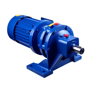
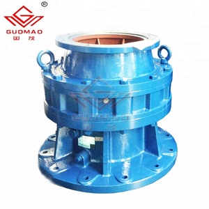
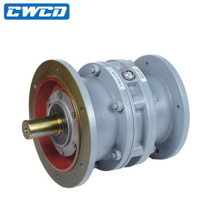
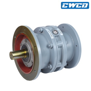
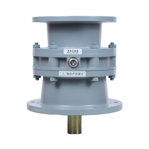
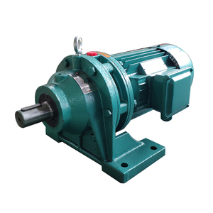
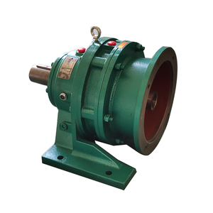
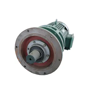
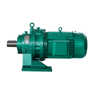
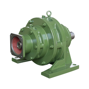
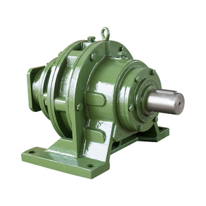
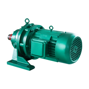
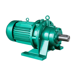
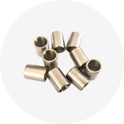
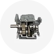
Types of bwd1 cycloid reducers
Cycloid gears are epicyclic gear systems, which reduce the speed and increase the torque. They consist of a high elliptical cam, a cycloidal output disc, an input pin and a set of output pins, cycloid. There are various kinds of cycloidal reducers, including the bwd1 cycloid reducer, which result in different gear ratios ranging from the lowest 1:1 ratio to the highest 100:1 ratio.
Their reduction mechanism is different from simple worms or planetary gear mechanisms. Nowadays, two-dimensional and three-dimensional applications of cycloidal reducers are exploited. Here are the common bwd1 cycloidal reducers based on structure:
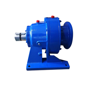
- 1st structure type - External structure: In external cycloid drives, the cycloid discs rotate around the derived centre of the path of the pins which is set on the epicyclic set. Such drives are simple in design but result in low compactness, and thus they suit only low-output torque applications.
- 2nd structure type - Internal structure: Internal cycloidal drives are more compact since the cycloid discs rotate within the set, and the pins are attached to the epicyclic set. This leads to a higher ratio and thus suits more applications where compactness is important next to functionality.
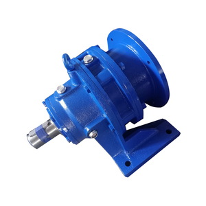
- 3rd structure type - Orbital: Orbital cycloid drives use pins to guide the motion of the cycloid discs more effectively. While being the most complicated in structure, they provide the highest output torque and the best reduction ratio. They are, however, only applied in highly professional engineering fields.
- 4th structure type - Cycloidal gear set: This type comprises only the cycloidal gears and associated elements without the carrier. The reduction occurs only by interlocking the cycloidal gear with the output shaft.
Industrial applications of bwd1 cycloid reducers
Cycloidal gearbox applications have advanced from simple reduction and torque multiplication functions to more demanding usage. In particular, the bwd1 cycloidal speed reducer is used in high-technology and fine-mechanical departments because of its high reduction ratio, constancy, and efficiency.
- Precision engineering: Cycloid drives are incorporated into CNC machines and robotic arms, where exact rotational control is necessary. They diminish the motor speed while increasing the torque supplied to the cutting tool for example.
- Robotics: In robot joints and actuators, accuracy and power density are main concerns. Cycloid drives provide compactness and high-output torque, making them ideal for humanoid robots and industrial arms carrying heavy objects or executing fine work under its weight.
- Aerospace: In satellite attitude control systems or landing gear mechanisms, compactness and lightness are desired features. Cycloid drives, particularly due to their ight weight and hability to work under extreme temperatures, are fit for such applications.
- Renewable energy systems: The efficiency of cycloid drives makes them very useful in wind or tidal energy converters. They help convert the low-speed, high-torque rotational motion resulting from wind or tides into high-speed motion to drive electrical generators, hence effective energy conversion.
- Marine systems: Cycloid drives are applied in propeller systems, where high efficiency and the ability to withstand harsh ambient conditions are demanded. Their potential to reduce engine speed while increasing the torque directed to propellers is of great interest.
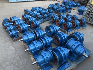
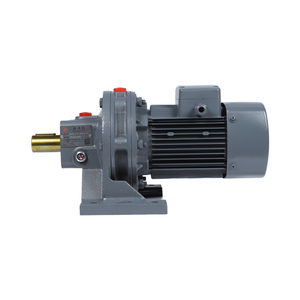
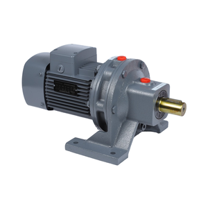
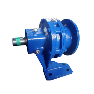
Key specifications and features of bwd1 cycloid reducers
Even if there are many kinds of bwd1 cycloidal reducers in use, they have some essential common features and parameters determining their performance characteristics. Some of the general features are:
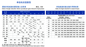
- High reduction ratio: The reduction ratios of cycloid reducers range anywhere from 1:1 to 100:1, sometimes more. This means they can considerably reduce output speeds while producing high torque.
- High efficiency: Their efficiency is usually about 94% to 96% - even in high reduction ratios, there is little wasted energy as heat. This makes them suitable for energy-conscious applications.
- Compact size: BWD1 Cycloidal reducers can provide high speed, low inuch torque due to the unique mechanism hence requiring less space as opposed to other speed reducers.
- Multi-pin design: The output pins of the cycloidal disc are connected to the eccentrically set input pins of the output shaft. This completes one full rotation of the input shaft and enables the cycloidal disc to rotate a fraction only of its full rotation, thus resulting in reduction.
- Load distribution: Since there are more than one pin in contact with the cycloidal disc at any one time, the meshing teeth are loaded evenly. This lowers the scraping, increases combining efficiency, and wears out less.
- Output shaft: The output shaft typically features a flange for connection to the load. Some designs offer multiple-output orientations for flexibility in installation.
How to choose/buy bwd1 cycloid reducers
When purchasing or selecting a cycloid pump speed reducer, there are important factors to bear in mind. There are operational requirements, which include load torque, speed range, and direction of rotation. These define the type of reduction needed.
Then, the possible compatibility with the existing system, how the surrounding or environmental conditions are, should be considered. While cycloid speed reducers can be exposed to harsh conditions, such as humidity, dust, extreme temperatures, or even water in some application scenarios, they are specially designed to suit such conditions.
Check features like efficiency, backlash, output torque, and housing materials, as these will determine performance. While most features do not affect the functionality, they offer additional benefits, such as the presence of an oil seal, which will help reduce or eliminate oil leak incidences and thus increase the life of the reducer.
Once the right reducer is found, proper installation is needed; the user should avoid overloading and check the alignment. They should also perform regular checks and maintenance services to enhance the life span of the reducer.
Going for a known and trusted brand or manufacturer is important since a cycloid speed-reducing unit is a long-term investment tool in any business or industry. The manufacturers of these products usually provide warranties and additional services that may come in handy later on, should a need arise.
Q&A
Q1. What is the main part of a cycloid speed reducer?
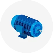
A1. The main parts of a cycloid speed reducer include the cycloid discs, the input shaft, the output shaft, the output pins, and the housing. Together, they form a compact and efficient speed-reduction mechanism.
Q2. Are bwd1 cycloid reducers energy-saving?
A2. Yes. Thanks to their high efficiency rates (up to 96%) - only a small amount of input energy is converted to waste as heat. This makes them ideal for energy-saving operations.
Q3. Can a bwd1 cycloid reducer function in high temperature?
A3. Yes, bwd1 cycloid reducers are manufactured to operate in extreme temperatures, both high and low. They are constructed using strong materials such as stainless steel and bronze to withstand such temperatures.
Q4.Here can bwd1 cycloid reducers be applied?
A4. bwd1 cycloid reducers are typically applied in aerospace, marine, and energy industries, which require efficiency, compactness, and durability against extreme temperatures and environments.
Q5. What creates backlash in a cycloid speed reducer?
A5. Backlash is the slight rotational movement of the output shaft that does not cause corresponding movement in the input shaft. It is primarily caused by the looseness between the gears or mechanical components in a mechanism.
Q6. What are some future trends for cycloid reducers?
A6. Future trends for cycloid reducers include going for greener and more efficient technologies, increasing demand for automation and robotics, advancements in materials and designs, and increased use in renewable energy systems, which improves their performance.


 浙公网安备 33010002000092号
 浙B2-20120091-4